


Troubleshooting Common SFP Module Issues

Today’s global networks are built on optical communication, with data transmitted through optical modules and fiber optic cables. They are the foundation of the network world. SFP optical modules are precision devices, and various faults may inevitably occur during operation. These faults can affect network stability and, in severe cases, cause network interruptions, resulting in losses. Therefore, it is important to be proficient in identifying and troubleshooting common fiber transceiver sfp module faults, and to resolve them effectively.
Physical Connection and Hardware Problem Troubleshooting and Solutions
Optical modules operate at the physical layer, and physical faults are the most common type of issue during use. Since fiber connectors are highly precise, incomplete connections or contamination and damage on the fiber end face can affect the normal transmission of optical signals, leading to link flapping or even disconnection. These faults can be identified and located through visual inspection and the built-in DDM function of the optical module. However, locating the fault does not always mean it can be resolved—if the hardware is damaged, the issue can only be fixed by replacing the module. Common physical layer faults include the following:
SFP Module Has No Received Optical Signal Due to Fiber Fault
Frequent fiber faults are a common cause of SFP not working. Common issues encountered in actual use include:
- Improper connection between the fiber connector and the SFP module interface
- Dirty or damaged fiber endface
- Fiber breakage
- Poor fiber quality and excessive transmission loss
The corresponding troubleshooting and solutions are as follows:
- Fiber connector is not properly connected to the SFP module interface. This can be detected by visual inspection, and further confirmed by reading the transmit optical power from the module’s DDM information. The solution is to unplug the fiber and reinsert it into the SFP module interface until a “click” sound is heard, indicating the fiber connector and SFP module are properly connected.
- Contamination or damage on the fiber end face requires the use of a fiber end-face inspection tool. Using this tool, the fiber end face can be directly observed. Contamination can be cleaned with fiber cleaning wipes. If the fiber end face is damaged, the fiber must be replaced. If the SFP module interface port is damaged, the SFP module needs to be replaced.
- Fiber breakage is a serious fault. Re-splicing long-distance broken fibers involves high cost. Troubleshooting fiber breaks requires a light source, optical power meter, and visual fault locator (red laser pen). After fiber breakage, the optical signal is very weak. A fixed-power light source is used to send light through the fiber, and an optical power meter measures the received power to confirm the break. The visual fault locator pinpoints the break location for re-splicing. For short-distance fibers, which have lower value, direct replacement is feasible.
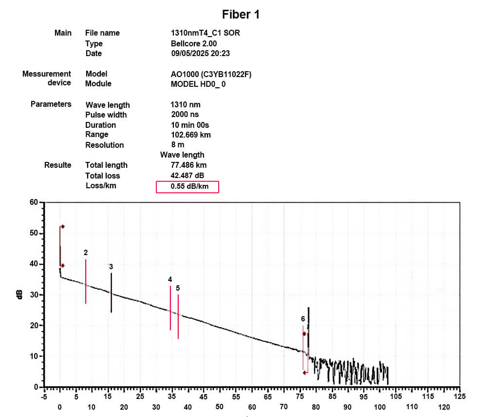
- Poor fiber quality and high transmission loss troubleshooting requires an optical power meter or OTDR. The actual fiber attenuation is determined by calculating the difference between emitted and received optical power; lower attenuation indicates better fiber quality. If the fiber quality is poor and attenuation is high, the fiber should be replaced or a higher-power SFP module with a larger link budget should be used.
Hardware Problems Cause the SFP Module to Be Unusable
Hardware problems can be said to be the most serious problems, which are basically unsolvable. There are two common hardware failures:
Hardware physical incompatibility
Physical incompatibility will directly cause the module to be unusable. If you encounter these problems during operation and maintenance, you can only solve them by replacing the module.
- The module cannot be inserted into the device port because the physical dimensions do not match.
- The device does not support the SFP module being used, and the module is not recognized after being inserted.
- The module is functioning normally, but a CRC error or link flapping occurs during use.
Physical hardware damage of the module
Module damage is a type of fault that must be strictly avoided during use. Physical damage to optical modules can present in various ways, such as DOM showing no bias current, no response when the module is inserted into a switch, no received optical power, or a fixed received optical power value. When using SFP optical modules, it is essential to strictly follow proper handling procedures. Touching the module’s golden fingers is strictly prohibited, and anti-static precautions must be taken during operation. For long-distance modules, it is important to ensure that the received optical power does not exceed the overload threshold of the module, to prevent damage caused by excessive optical power. If physical hardware damage occurs during maintenance, the only solution is to replace the damaged module.
Software Compatibility Problem Investigation and Solutions
To ensure stable operation and maximize product profit, some equipment vendors implement compatibility requirements on their devices. The internal compatibility codes of SFP optical modules vary across different brands. Most vendors embed not only standard protocol information but also proprietary data in the module’s EEPROM. If the encoded information written during production does not meet the device’s compatibility requirements, it can lead to faults. Currently, device compatibility levels can be roughly classified into three tiers based on brand, with Tier 1 being the most restrictive and Tier 3 the least.
Tier 1 Compatibility
Vendors such as Cisco, Arista, and HP fall under Tier 1. If the SFP module coding does not comply with the device’s compatibility requirements, the module will not function, and in some cases, the port may even be disabled.
Tier 2 Compatibility
Vendors such as H3C, Huawei, and Juniper belong to Tier 2. If the module coding does not fully comply, the device may generate warning logs or disable certain features, but the module can still operate normally.
Tier 3 Compatibility
Devices with Tier 3 compatibility have no strict coding requirements. As long as the SFP module complies with the SFF-8472 standard, it can be used. Brands like Finisar, Netgear, and Ubiquiti, along with many smaller vendors, typically fall into this category and impose no compatibility restrictions.
When encountering compatibility issues, the first step is to verify whether the physical link is functioning properly and whether the module is supported by the device. Once confirmed, check the device brand and review the system logs via the CLI interface. Most devices with compatibility enforcement will log messages indicating that the inserted module is unsupported. To resolve such issues, the SFP module needs to be reprogrammed with a compatibility code that matches the target device. For OEM modules, this code can often be provided by the module supplier. If not available, the only solution is to purchase an original branded module, which is guaranteed to work but comes at a significantly higher cost.
Troubleshooting and Solutions for Configuration Issues
Switches offer a wide range of features to meet the requirements of different network environments. However, enabling all features by default can be inconvenient for users with light workloads. Therefore, switches are usually shipped with only the basic functions enabled, and additional features must be manually configured. This inevitably leads to configuration errors, which can prevent the link from being properly established. Common configuration error types include the following:
- Device Port Configuration Errors
Examples include ports being manually shut down, mismatched port speed and duplex mode, or FEC being disabled or misconfigured on high-speed modules above 100G. These issues can be diagnosed by accessing the CLI and using commands to check the configuration. Once the problem is identified, apply the correct settings to resolve it.
- Device Protocol Configuration Errors
There are various types of protocol-related configuration errors. Common examples include failed stacking or unsuccessful OSPF neighbor establishment. These problems also require checking configuration details via CLI commands and correcting them accordingly to restore proper operation.
Troubleshooting and Solutions for Usage Environment Problems
SFP optical modules are categorized into industrial-grade and commercial-grade types. Standard SFP modules are typically used in indoor data centers, where commercial-grade modules are sufficient. However, customer environments are not always fixed, and there may be situations where the modules are deployed in harsh conditions. In such cases, even if the physical link, compatibility, and device configuration are all correct, commercial-grade modules may still fail to operate reliably. Forcing them to work under these conditions may even result in module damage, which must be avoided. In harsh environments, only industrial-grade modules can ensure stable and reliable operation.
Conclusion
Review of SFP Optical Module Troubleshooting Process
When encountering an optical module fault, troubleshooting should begin at the physical layer and proceed step by step toward the protocol layer. This layered analysis is necessary because data first enters through the physical layer and is transmitted upward. If there is an issue at the physical layer, the link will definitely not be established. Following this approach helps avoid wasting time in the wrong direction, allows the fault to be resolved as early as possible, and prevents extended service interruptions that could lead to further losses.
Summary of Key Points for Solving SFP Optical Module Troubleshooting
- Ensure the cleanliness of the fiber end face and module interface
Clean optical surfaces are essential to ensure proper transmission of optical signals, which is a key factor for the stable operation of optical modules.
- Check DOM information in a timely manner
DOM diagnostics provide a direct way to assess the working status of optical modules. Most module faults can be identified through DOM data.
- Verify compatibility
Compatibility coding is critical for the device to recognize the optical module. Correct coding ensures that the module functions properly on the switch. Many module faults are caused by incorrect compatibility coding.
- Carefully check configuration
Only correct configuration can ensure proper switch operation and maintain stable network transmission.
Share on Social:


- PREV: Discover the InfiniBand and InfiniBand Switch
- NEXT: Null