


Everything You Need to Know About Single Mode Fiber Optic Cable
What is Single Mode Fiber?
Basic Introduction to Single Mode Fiber Optic Cable
Fiber optics are an indispensable part of modern communication networks, playing a vital role in signal, data, and network transmission. Fiber optic single mode serves as the core transmission medium for long-distance, high-capacity optical communication networks. Its original design aimed to address the modal dispersion issue in multimode fibers: when optical signals travel through multimode fibers, light waves of different modes spread due to varying propagation paths, causing signal pulse broadening and limiting transmission distance and speed.
Single Mode Fiber Optic Cable achieves its performance by reducing the core diameter to 8–10 μm (approximately 1/10 the thickness of a human hair), allowing only the fundamental mode to propagate at specific wavelengths, thereby eliminating modal dispersion entirely. This characteristic makes sm fiber the dominant choice for metropolitan area networks (MANs), backbone networks, and submarine optical cables.
Physical Structure and Light Transmission Principle
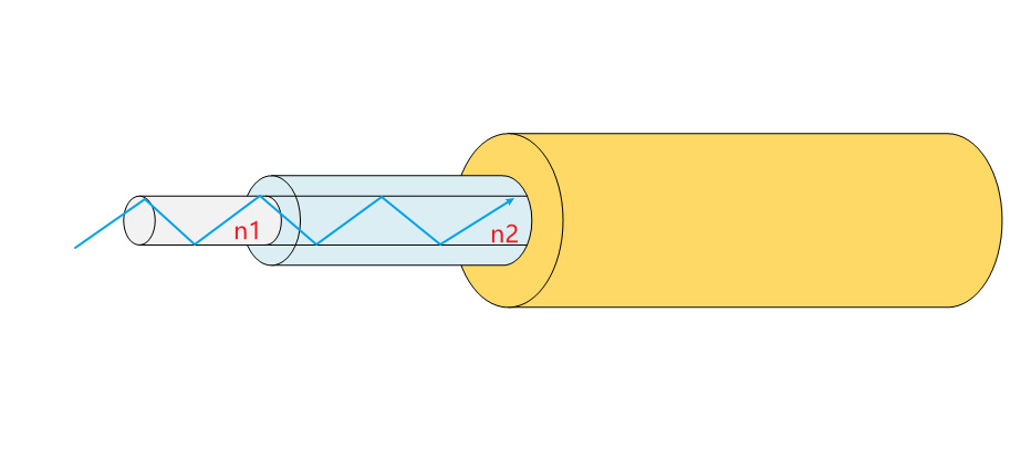
The physical structure of single-mode fiber consists of three layers:
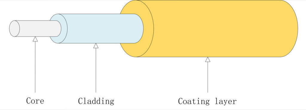
Core: Diameter of 8–10 μm, made of high-refractive-index glass (germanium-doped silica).
Cladding: Diameter of 125 μm, composed of low-refractive-index material (pure silica), enabling light confinement through refractive index contrast.
Coating layer: Diameter of 250 μm, primarily made of acrylate resin, designed to protect the fiber from external damage, enhance flexibility, and reduce bending loss.
Fiber-optic communication relies on the principle of total internal reflection (TIR):
When light enters the fiber core, the higher refractive index (n₁) of the core (compared to the cladding’s n₂) and the lower attenuation of the core cause the light to undergo continuous TIR. This allows the light signal to propagate through the fiber with minimal loss until it reaches the far end.
Key Parameters of Single-Mode Fiber
Mode Field Diameter (MFD, d)
The Mode Field Diameter (MFD) refers to the diameter of the optical power distribution in the fiber’s cross-section. At 1310 nm, the MFD is typically 9–10 μm. Mismatch in MFD between connected fibers can lead to connector loss, with every 0.5 μm deviation increasing loss by 0.1 dB. In simple terms, the MFD should closely match the core diameter of the single-mode fiber to minimize insertion loss.
Cutoff Wavelength (λc)
The cutoff wavelength is the critical wavelength at which a fiber transitions from multimode to single-mode operation—meaning it is the minimum wavelength required for single-mode transmission. If the signal wavelength is shorter than the cutoff wavelength, the fiber cannot maintain single-mode propagation.
Testing method (per industry standards):
A 2-meter fiber sample is bent with a 140 mm radius, and the cutoff wavelength is determined when the fundamental mode attenuation is ≤0.1 dB.
Attenuation Coefficient (α)
The definition of the attenuation coefficient is: the attenuation of optical signal power per kilometer of fiber, measured in dB/km. The typical attenuation coefficient is 0.35 dB/km at a wavelength of 1310 nm and 0.20 dB/km at 1550 nm. Ultra-low loss fiber (ULL), manufactured using a pure silica core process, achieves an attenuation coefficient of 0.16 dB/km.
The primary sources of fiber optic loss are intrinsic and extrinsic losses. Intrinsic losses arise from material impurities (such as residual OH⁻ ions) and Rayleigh scattering (caused by metal ions in the air). Extrinsic losses result from external factors like bending and connector contamination. Therefore, to produce low-attenuation fiber, an extremely stringent pure silica core process must be employed to minimize impurity content.
Single-Mode and Multimode Fiber
Key Parameter Differences (Including Data Chart)
The core differences between sm fiber and multimode fiber are as follows:
Core Diameter
Multimode fiber typically has a core diameter of 50–62.5 μm, supporting multiple light transmission modes. However, it suffers from significant modal dispersion, making it suitable only for short-distance transmission.
Fiber optic single mode has a much smaller core diameter of 8–10 μm, allowing only one light transmission mode. By reducing the core diameter, modal dispersion is eliminated, enabling long-distance transmission.
Operating Wavelength
Multimode fiber commonly operates at 850 nm and 1300 nm wavelengths.
Fiber optic single mode primarily operates at 1310 nm and 1550 nm wavelengths, with the 1550 nm band offering the lowest attenuation coefficient.
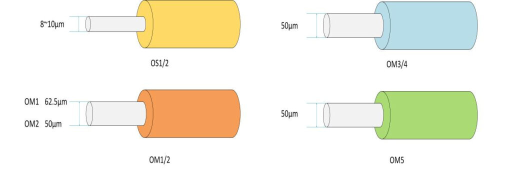
Jacket Color
Single-mode and multimode fibers can usually be distinguished by their jacket colors:
Single-mode fiber typically uses a standard yellow jacket.
Multimode fiber varies by type:
Orange jacket (OM1/OM2),Aqua blue jacket (OM3/OM4),Lime green jacket (OM5).
Bandwidth Capacity and Transmission Distance Analysis
The bandwidth capacity and transmission distance of single-mode fiber (SMF) and multimode fiber (MMF) differ significantly due to their physical characteristics and dispersion mechanisms.
Single-mode fiber has a theoretical bandwidth exceeding 10 Tbps, with commercial systems already supporting 400G and 800G single-wavelength transmission. Its low-dispersion mechanism enables ultra-long-distance, high-capacity data transmission. At sub-100G rates, it supports 40–120 km of transmission. For high-speed 400G/800G applications, coherent transmission technology allows 80–120 km of unrepeatered transmission.Multimode fiber, limited by modal dispersion, has a maximum bandwidth of 28,000 MHz·km (OM5). It can achieve 550 m at 10G speeds, but in high-speed scenarios, its reach is restricted to a maximum of 150 m. However, compared to SMF, MMF offers lower costs, making it suitable for short-distance, cost-sensitive deployments.
Cost-Benefit Comparison
As mentioned above, multimode fiber is less costly than sm fiber, mainly due to differences in equipment hardware costs, light sources, and material costs. fiber optic single mode requires laser light sources such as DFB (Distributed Feedback) and EML . Laser light sources emit single-wavelength light, enabling precise control, but the corresponding optical modules are more expensive—single-mode optical modules are typically more than three times the cost of multimode ones. Additionally, higher precision is required for fusion splices and connectors, with errors needing to be <0.3μm.
In contrast, multimode fiber mostly uses FP (Fabry-Perot) or VCSEL (Vertical-Cavity Surface-Emitting Laser) light sources, which are lower in cost. However, this leads to modal dispersion, limiting transmission distance. The corresponding optical modules are generally cheaper, and the larger core diameter of multimode fiber allows looser connection tolerances, reducing installation complexity.
Different fibers and optical modules can be selected based on scenarios to improve cost-effectiveness:
For short distances <500m, multimode fiber offers advantages. For example, in data center internal equipment interconnection, using multimode modules and fibers significantly reduces costs.
For cross-data center or cross-regional interconnection, usually the transmission distance is greater than 2km, Single Mode Fiber Optic Cable can reduce the number of repeaters, long-term operation and maintenance costs are relatively lower, more suitable for MAN deployment.
Evolutionary Route of Single-Mode Fiber Technology
Differences between OS1 and OS2 Standards
Single-mode fiber is currently divided into two categories: OS1 and OS2, the differences are mainly reflected in the manufacturing process, transmission performance and application scenarios:
First of all, on the standard, OS1 follows the ITU-T G.652A/B standard, mainly supports O-band (1310nm) and C-band (1550nm), and can not use the E-band (1360~1460nm) due to the failure to eliminate the water peak at 1383nm. On OS2, based on G.652C/D standard, the water peak is eliminated by improving the manufacturing process, and four bands of O, E, S and C (1325~1560nm) are supported to provide wider spectrum resources for WDM technology.
Secondly, OS1 has a maximum attenuation of 1.0dB/km in the 1310/1550nm band, with a typical transmission distance of ≤10km, while OS2’s attenuation has been reduced to 0.4dB/km, supporting ultra-long-distance transmission of up to 200km, which is especially suitable for submarine fiber-optic cables and cross-city backbone networks. And OS1 and OS2 sheath structure is not the same, OS1 fiber with tight sleeve structure, suitable for indoor short distance cabling, OS2 for loose sleeve structure, higher tensile strength, more suitable for outdoor complex environment.
Despite its superior performance, OS2 is still widely used in LANs and traditional campus networks because the cost of OS1 is 30% lower than that of OS2. However, with the popularization of 400/800G high-rate coherent technology, OS2 has become the only choice for ultra-100G long-distance transmission.
Evolutionary Path from G.652 to G.657
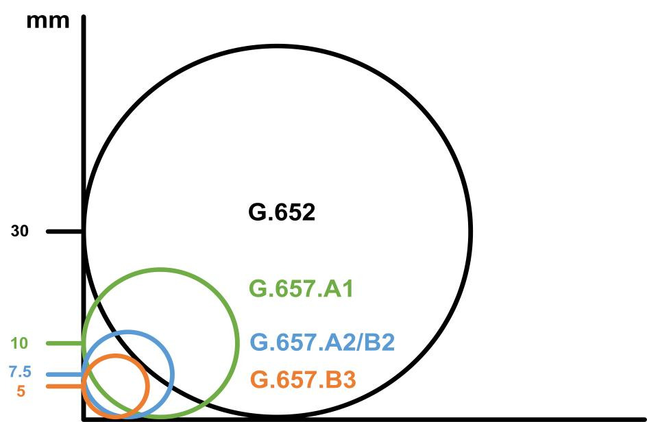
The standard for Single Mode Fiber Optic Cable has iterated from G.652 to the current G.657, reflecting a technological leap from basic transmission performance to environmental adaptability. At the time of the G.652 standard, the main purpose was to break through the elimination of water peaks and full-band optimization. The early G.652A/B standard only supported O/C bands with high polarization mode dispersion coefficients, and was limited to system applications below 40G. The subsequent G.652D standard eliminates water peaks and becomes the mainstream choice for metro and backbone networks, supporting wider bands.
Bending loss was once the biggest obstacle to fiber optic single moder deployment in access networks, G.657.A1 standard update, for the first time, the minimum bending radius from the G.652 standard of 30mm compressed to 10mm, additional loss in the 1550nm band ≤ 0.75dB, to promote the scale of the deployment of the FTTH, G.657.A2 is further optimized to 7.5mm bending radius, additional loss Reduced to 0.5dB, supporting high-density cabling, G.657 through the trench-assisted refractive index profile design, adding a low refractive index ring layer outside the cladding layer, suppressing the optical leakage generated during bending, and realizing an exponential increase in bending resistance. Secondly, the coating layer material is also a point that can not be ignored, the use of ultra-low modulus coating materials, such as polyimide, the fiber in the bending of the stress distribution is more uniform, reducing the micro-bending loss, and in the macro-bending loss, the definition of a new indicator: the fiber to 7.5mm radius loosely wrapped around 1 circle, instead of G.652 in the radius of 30mm loosely wrapped around the 100-turn test, more closely related to the actual cabling scenarios.
G.657’s bend-insensitive technology is directly contributing to the proliferation of whole-house fiber FTTR and 5G pre-transmission networks. Through continuous innovation from basic performance to environmental adaptability, single-mode fiber is evolving from a data transmission medium to the nerve of optical networks, supporting the ultra-high-speed needs of future 6G and arithmetic networks.
Typical Application Scenarios
With low attenuation, high transmission capacity and high anti-jamming ability, single mode fiber has become the core transmission medium of modern communication networks and has an irreplaceable role in various fields. D and G.654.E single-mode fiber can reduce the use of repeaters by virtue of its ultra-long transmission distance, such as in the long-distance backbone network and submarine cable system. In addition, in the signal transmission system equipped with EDFA (Optical Signal Amplifier) and DRA (Distributed Raman Amplifier), 400Gbps (more than 2000km) long-distance transmission can be achieved by laying G.654.E optical fiber, supporting the cross-city area of the long-distance transmission, and supporting the cross-city area of the long-distance transmission, and supporting the cross-city area of the long-distance transmission. 2000km) long distance transmission, supporting data transmission across cities, provinces and even countries. In FTTH fiber to the home, its ultra-low bending loss under the G.657 standard can cope with complex cabling environments and support users to deploy invisible fiber to the wall. According to the statistics of China Mobile, after the adoption of G.657 optical fiber, the failure rate of FTTH has been reduced from 50% to less than 5%.
In the data center interconnection scenario, single-mode fiber can achieve 400G/800G ultra-high data throughput within a limited distance, and in the data center long-distance transmission, compared with multi-mode fiber can effectively reduce the relay point, which greatly reduces the subsequent maintenance costs.
Fiber Optic Single Mode Selection Guide
Attenuation Specification Selection Strategy
Single-mode fiber attenuation coefficient will directly affect the transmission distance and system cost, in the conventional campus network, metro network scenarios, G.652.D fiber attenuation coefficient in the 1550nm band is 0.2dB/km, enough to meet the deployment environment, no need to blindly pursue the ultra-low insertion loss. In ultra-long distance scenarios, such as backbone networks, submarine cables, etc., you need to use G.654.E ultra-low insertion loss fiber, which can significantly reduce the deployment density of repeaters and reduce maintenance costs.
Comparison of Connector Types
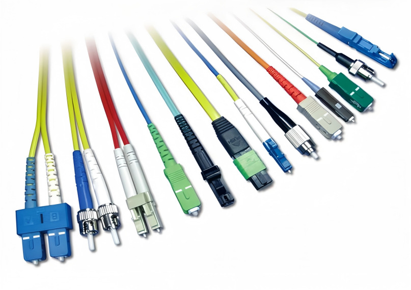
When selecting a single-mode fiber, the finished fiber is usually equipped with connectors, common connectors are LC, MPO, SC, FC, ST, etc..
LC connector for miniaturization design, there are simplex and duplex points, simplex is common in BIDI type module, LC connector fiber is often applied to data centers and other high-density cabling scenarios, the number of times of plugging and unplugging is generally greater than 500 times.
MPO connector is usually used for high speed, such as 400G, 800G single-mode DR optical modules, through the multi-core integration of the function of transmitting higher bandwidth, using the push-pull design, commonly used in data centers backbone network cabling.
Common in our homes in the multimedia box for the SC connector fiber optic, SC connector for the square snap structure, strong stability, compared to LC connectors are less prone to damage, widely used in FTTH and access networks, but due to the large size, not suitable for high-density cabling scenarios.
FC interface for the metal round threaded, threaded locking, excellent seismic performance, usually applied to industrial environments, such as base stations, railroad communications and other infrequent plugging and unplugging and higher stability requirements of the scene.
There is also an uncommon ST connector, for the snap type rotary connector, has been gradually replaced by SC / LC and other connectors, usually used in the past for the old LAN and monitoring systems, with good tensile strength.
| Connector type | Structural characteristics | Connection method | Usage Scenarios | Advantages and disadvantages |
| LC | Small square ceramic ferrule (1.25mm) | Push-pull clasp | High-density environments (e.g., data centers, switches) | Compact size, high density; requires cautious plugging/unplugging |
| MPO | Multi-core rectangular connector | Push-pull latch | High-speed networks (400/800G), data center backbones | Multi-core integration, space-saving; complex installation |
| SC | Square ceramic ferrule (2.5mm) | Push-pull direct insertion | Telecom networks, FTTH, ordinary machine rooms | Stable plugging/unplugging, low cost; larger volume |
| FC | Metal threaded shell + ceramic ferrule (2.5mm)) | Rotating thread locking | High-vibration environments (e.g., industrial, military) | Strong anti-vibration capability; slow installation, high cost |
| ST | Clasp-type metal shell (2.5mm) | Clasp rotating locking | Legacy LAN, monitoring systems | High tensile strength; gradually replaced by SC/LC |
Selection of Bending Resistance Grade
In the purchase of optical fiber, there is an important point is to pay attention to the optical fiber bending resistance class, that is, the minimum bending radius. Fiber bending grade is mainly defined by the ITU-T standard G.657, the standard for single-mode fiber bending performance classification, specifically divided into G.657.A and G.657.B two series, common bending grade is as follows:
| Fiber Type | Bending Resistance Grade | Minimum Bending Radius (Short-term/Long-term) | Compatibility | Typical Application Scenarios |
| G.657.A1 | Ordinary Bending Resistance | 10mm/15mm | Compatible with G.652.D (Traditional Single-mode) | Ordinary FTTH, Machine Room Cabling |
| G.657.A2 | Medium Bending Resistance | 7.5mm/10mm | Compatible with G.652.D | Home Cabling, Complex Pipelines |
| G.657.B2 | High Bending Resistance | 5mm/7.5mm | Partially Compatible with G.652.D | High-density Cabling in Data Centers, Micro Cables |
| G.657.B3 | Ultra-high Bending Resistance | 5mm/7.5mm | Incompatible with Traditional Fibers | Extreme Bending Scenarios (e.g., Corners, Inside Equipment) |
Certification Standards Verification Points
Common certification of optical fiber is mainly UL/ETL/IEC certification, in line with the certification standards, better ensure the reliability and compliance of optical fiber.
UL certification is common UL 1666, used to assess the flame spreading performance of cables in vertical installation, mainly for OFNR grade cables, applicable to vertical shaft wiring in buildings, with medium flame retardant performance; UL 910 is for OFNP grade cable combustion test, requiring the highest flame retardant, applicable to air circulation space, such as air conditioning ducts, ceiling cladding, etc.; UL 1581 is a general-purpose UL 1581 is a general cable combustion test standard, covering smoke density, toxicity and other parameters, commonly used in the evaluation of LSZH low-smoke halogen-free materials.
ETL certification is similar to UL, covering electrical safety and flame retardant performance of cables, its test standards are usually consistent with UL, and UL certification in the U.S. market has the same effect, but the certification process is relatively flexible.
IEC standards for international standards, general export projects to be mandatory to comply with the common IEC 60332, used to assess the vertical combustion performance of the cable, divided into IEC 60332-1 (single cable test) and IEC 60332-3 (bundled cable test); IEC 60754 is mainly aimed at the toxicity of the cable combustion gas release test, LSZH cables are required to pass this standard; IEC 61034 for the smoke density test, requiring the smoke produced when the cable burns light transmission rate ≥ 60%.
When shopping for fiber optic cables, we need to confirm whether the product has passed the mandatory certification of the target market, and require the supplier to provide relevant test reports. In terms of usage scenarios, data center/computer room environments give priority to OFNP grade cables to ensure high flame retardancy and low smoke toxicity; for office buildings and residences, OFNR can satisfy the demand, taking into account the cost and performance; in relatively confined places, such as subways, tunnels, hospitals and so on, LSZH cables must be used, in line with IEC 60754/61034 standards.
Frequently Asked Questions (FAQ)
Q: Can fiber optic single mode be used on multimode modules?
A: Fiber optic single mode are generally not recommended for use on multimode modules. In the article we talked about sm fiber core diameter is fine, about 9μm, multimode modules (such as 850nm wavelength VCSEL light source) light-emitting dispersion angle is large, the light beam is difficult to effectively coupled into the single mode fiber, which will result in serious optical power loss, resulting in a significant reduction in transmission distance or even communication interruption. And multi mode module and single mode fiber optimal operating wavelength (multi-mode 850/1300nm, single-mode 1310/1550nm) does not match the wavelength of the fiber under the significant difference in transmission characteristics, forced to use the performance will lead to failures, so we need to match the corresponding type of optical fiber and the module to ensure normal communication.
Q: If I need to go from an LC interface optical module to a panel whose interface is SC, is it possible?
A: Of course you can, there are usually single mode patch cables specially made for LC interface to SC interface, such as LSOLINK’s OS2-S-LCU-SCU patch cables, which can fully meet your needs.
Q: Why are most of the fiber optic single mode used for optical modules LC interfaces?
A: Fiber optic single mode used in optical modules mostly adopts LC interface, mainly because of its compact size and high density, which is suitable for high-density deployment of data centers, switches, etc. The LC interface is of plug-and-play design, which is easy to operate and occupies little space, and can integrate more ports in the limited panel space. At the same time, the high precision of the physical structure of the LC interface ensures the accurate docking of fiber optic single mode, reduces optical loss, and meets the requirements of single-mode transmission for low attenuation and high stability. In addition, the LC interface has a high degree of standardization, strong compatibility with mainstream optical modules, and has become the industry’s default choice, so it is widely used in single-mode fiber connection.
Q: How to maintain the sm fiber patch cord to extend the service life?
A: When using sm fiber optic patch cords, you need to pay attention to the degree of cleanliness of the fiber optic end face as well as to avoid unnecessary bending, use special cleaning tools, such as fiber optic cleaning pens, compressed air canisters, etc. to regularly clean up the connector end face, to avoid signal attenuation caused by dust. Need to pay attention to the bending radius is in line with the norms, beyond the bending radius will produce micro-bending loss, and even lead to fiber core breakage. In the daily insertion and removal process, you need to hold down the buckle for insertion and removal, to avoid damage to the ceramic core in the insertion and removal, do not use the fiber optic patch cord attention to cover the dust cap, and stored in a dry, ventilated, non-extruded environment.


