


Understanding the Digital Diagnostic Monitoring (DDM)
In the current era when the digital wave is sweeping the world, the stable operation of network infrastructure is of vital importance. As the core component for data transmission, the performance of optical modules directly affects network efficiency. Digital Diagnostic Monitoring (DDM) technology emerged. How does it ensure the stable operation of optical modules? Now let’s take a closer look at this key technology.
What Is DDM of Optical Module?
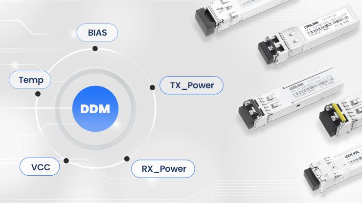
DDM stands for Digital Diagnostic Monitoring, which is an embedded monitoring technology. It collects the key operating parameters of the optical module in real time through the I2C interface. It functions as the “health monitoring system” of the equipment, enabling real-time monitoring of data such as the temperature, voltage, transmission/reception optical power, and laser bias current of the optical module. It also feeds the information back to the management system. The DDM technology not only alerts potential faults but also helps maintenance personnel remotely grasp the equipment status. It is widely applied in scenarios such as telecommunications networks and data centers, and has become one of the core technologies for ensuring the stability of optical communication systems.
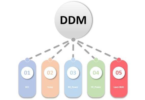
What Are the Main Parameters of DDM?
BIAS Bias Current
BIAS: BIAS refers to the direct current bias current provided to the laser or light-emitting diode in the optical module. Its function is to make the laser or light-emitting diode work in a stable state, ensuring the stable transmission of optical signals. The size of the bias current directly affects the working performance of the laser, such as output optical power, threshold current, etc. If the bias current is inappropriate, it may cause the laser to work unstably, resulting in power fluctuations, increased noise, and other problems, thereby affecting the quality of the optical signal. During testing, it is necessary to precisely adjust and monitor the bias current to ensure the transmission performance of the optical module.
Module Voltage
The real-time voltage of the optical module can be seen in the DDM of the optical module. It refers to the power supply voltage provided by the internal components of the optical module when they are working normally, which is the fundamental condition for ensuring the stable operation of its optical-electrical signal conversion function. It is usually measured in volts, and the common specification is 3.3V.
The core significance of the voltage parameters of the optical module is as follows: First, it provides energy for the active components within the module. For example, the laser needs a stable voltage to drive the emission of light signals. Insufficient voltage will cause unstable light power output or wavelength deviation, while excessive voltage may burn out the components; Second, it affects the signal processing accuracy. Analog-to-digital conversion, clock synchronization and other circuits are sensitive to voltage fluctuations. Unstable voltage will introduce noise and lead to an increase in bit error rate; Third, it is related to the module’s lifespan and reliability. Working in an environment that deviates from the nominal voltage for a long time will accelerate the aging of electronic components and even cause sudden failures.
In practical applications, the voltage parameters of the optical module need to be precisely matched through the power adapter or the power supply system of the device motherboard. Moreover, most modules support digital optical monitoring functions, which can provide real-time feedback of the current working voltage value, facilitating the monitoring of power stability by maintenance personnel.
Emitted Optical Power
The emitted optical power of an optical module refers to the actual optical energy intensity output by the transmitting end TX of the module after converting the electrical signal into an optical signal. It is a key indicator for evaluating the performance of the optical module and is usually measured in dBm or mW, reflecting the strength of the optical signal. It directly affects the transmission quality of the optical communication system: if the power is too low, the signal will suffer severe attenuation during transmission through the optical fiber, making it difficult for the receiving end to decode correctly, leading to errors or even communication interruption; if the power is too high, it may damage the receiving end detector or trigger nonlinear effects in the optical fiber, worsening the signal. Its magnitude is determined by factors such as the type of optical module, laser technology, and transmission distance, and for longer transmission distances, the laser power used is usually higher.
Emitted optical power is a key indicator in DDM. In practical applications, a power margin needs to be reserved to ensure the stability of the link and the transmission distance, avoiding compatibility issues or equipment failures caused by abnormal power.
Receiving Optical Power
The receiving optical power of an optical module refers to the power level of the optical signal captured at its receiving end. It is usually measured in dBm and is a key parameter for evaluating the quality of an optical communication link. This parameter directly reflects the strength of the optical signal reaching the receiving end after transmission through optical fibers. If the power is too low, it is below the receiving sensitivity of the optical module, and the optical signal will be masked by noise, resulting in an increase in bit error rate or even communication interruption. If the power is too high, it may cause the photodetector to saturate and prevent accurate signal demodulation.
In practical applications, the real-time receiving optical power of the optical module can be viewed through the DDM function of the optical module to ensure it is within a reasonable range.
Real-time Temperature
The temperature range refers to the environmental temperature interval within which the optical module can operate normally. It usually includes the operating temperature range and the storage temperature range. The performance of the optical module is highly sensitive to temperature. Excessive heat or cold will affect its various parameters, such as the emission optical power, wavelength, sensitivity, etc. For example, high temperature may cause the threshold current of the laser to increase and the output power to decrease; low temperature may increase the noise at the receiving end and reduce the sensitivity. Therefore, in the design and testing of optical modules, the impact of temperature on their performance needs to be considered to ensure that the optical module can work stably within the specified temperature range and adapt to different application environments. Common temperature ranges for optical modules: commercial grade is 0~70℃, industrial grade is -40~70℃.
How to Locate Problems Through DDM?
SFF provides four specification setting values for each of the first five monitoring contents.
| Low Alarm | exceeded the lower limit of the set specifications, cannot ensure normal operation |
| Low Waring | exceeded the warning limit, but it can still operate |
| High Waring | exceeded the warning limit, but it can still operate |
| High Alarm | exceeded the set specification limit and cannot ensure normal operation |
By analyzing the DDM information, the relevant parameters are compared with the normal threshold values of the module to identify abnormal items. Some switches will mark the abnormal information, emphasizing the display by using plus and minus signs or different colors.
Conclusion
The DDM technology, with its powerful real-time monitoring and data analysis capabilities, has become the “guardian” ensuring the stable operation of networks in the optical communication field. From precise monitoring of key parameters to intelligent location of fault issues, DDM not only significantly improves the operation and maintenance efficiency, but also shifts the management of optical modules from passive response to proactive prevention. In today’s era of explosive growth in data traffic, mastering the core principles and application methods of DDM technology is an important path for enterprises to optimize network architectures and reduce operation and maintenance costs. In the future, as optical communication technology continues to evolve, DDM will also be continuously upgraded to provide reliable support for more complex network environments.
Frequently Asked Questions (FAQ)
Q: Must the optical module be replaced immediately when the DDM monitoring parameters exceed the normal range?
A: Not necessarily. When parameters are abnormal, the specific cause should be analyzed first. For example, a temporary temperature increase may be due to insufficient environmental heat dissipation, which can be resolved by improving ventilation. If the transmitted optical power consistently fails to meet standards and adjusting the bias current proves ineffective, then replacing the optical transceiver should be considered. It is recommended to make decisions based on historical data and multi-parameter correlation analysis.
Q: Do all optical modules support the DDM function?
A: Most optical modules support DDM functionality. For specific information, confirm with the manufacturer or check if the product specifications indicate DDM support.
Q: How often is DDM data updated?
A: The update frequency of DDM data depends on the optical module design and device configuration, typically ranging from once per second to once per minute. Some high-end products support customizable refresh intervals, allowing operation and maintenance personnel to flexibly adjust monitoring density according to needs, achieving more refined device management.
Share on Social:


