


Introduction
In current network communication, SFP optical modules are an indispensable physical foundation for building network channels. They form high-speed channels for optical signal transmission. Without optical modules, data cannot be stably transmitted over long distances. Therefore, to ensure their stable operation, it is necessary to closely monitor their various working parameters to ensure that SFP optical modules operate stably and healthily within the specified range. SFP optical modules have many working parameters, all of which are important. Today’s article will let us take a look at the transmit optical Tx Power and receive optical Rx Power of SFP optical modules.
What is Optical Power
Tx Optical Power
Tx power (transmission power) refers to the intensity of the optical signal output by the transmitting end of the optical module. However, in practical use, we adopt the average Tx power. The average transmission optical power refers to the optical power output by the light source at the transmitting end of the optical module under normal working conditions, which can be understood as the intensity of the light. The transmission optical power is related to the proportion of “1” in the transmitted data signal. The more “1”s, the greater the optical power. When the transmitter sends pseudo-random sequence signals, “1” and “0” are approximately equal in proportion. At this time, the power obtained through testing is the average transmission optical power, expressed in units of mW or dBm. In optical communication, we usually use dBm to represent optical power.
Rx Optical Power
Rx power (receiving optical power) refers to the average optical power range that the receiving component of the optical module can receive under a certain bit error rate (BER = 10^-12) condition. The unit is dBm. The upper limit of the receiving optical power is the overload optical power, and the lower limit is the maximum value of the receiving sensitivity. Here, we have learned about two important parameters of the optical module. Overload optical power and receiving sensitivity, both of these parameters directly affect whether the SFP optical module can work normally.
Overload Optical Power
Overload optical power, also known as saturation optical power, refers to the maximum average input optical power that the receiving component of the optical module can receive under a certain bit error rate (BER = 10^-12) condition. The unit is dBm. It should be noted that the optical detector will exhibit photoelectric current saturation under strong light irradiation. Once this phenomenon occurs, the detector needs a certain amount of time to recover. At this time, the receiving sensitivity decreases, and the received signal may be misjudged, resulting in error code phenomena. In simple terms, if the input optical power exceeds this overload optical power, it may cause damage to the equipment. During operation, it is necessary to avoid strong light irradiation as much as possible to prevent exceeding the overload optical power.
Reception Sensitivity
Reception sensitivity refers to the minimum average input optical power that the receiving end components of the optical module can receive under a certain bit error rate (BER = 10^-12) condition, and it is also measured in dBm. Generally, the higher the rate, the worse the reception sensitivity, that is, the larger the minimum received optical power, and the higher the requirements for the receiving end components of the optical module.
What Are the Functions of the Tx power and Rx Power of the SFP Optical Module?
Calculating the Theoretical Transmission Distance of the Optical Module
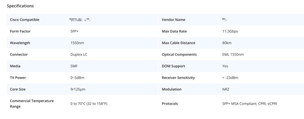
Once we know the TX power and RX power of the SFP optical module, we can use the optical power budget calculation formula: the minimum emission power minus the receiving sensitivity, to estimate the optical power budget of this optical module, and then calculate how far this SFP optical module can transmit. For example, the parameters of the LSOLINK 10G-SFP-ZR4 module are as follows: the emitted optical power is 0 to 5 dB, the received optical power is -20.9 dB to -4.9 dB, its overload point is -4.9 dB, and the receiving sensitivity is -20.9 dB. According to the optical power budget calculation formula, its optical power budget is 20.9 dB. Considering the attenuation coefficient of light at 1550 nm wavelength in standard single-mode optical fiber is 0.25 dB/km, then it can transmit 83 km, which can meet the 80 km transmission requirement. Of course, this is the theoretical transmission distance. In practical applications, the quality of the optical fiber link varies, and it is necessary to select the corresponding optical module with the optical power budget based on the actual link attenuation value, so as to achieve stable data transmission.
Confirm the Working Status of the Optical Module
When the module is operating normally, both its TX optical power and RX optical power will be within a specified range. By checking the reported TX optical power and RX optical power values from the DDM of the optical module, it is possible to determine whether the module is operating normally. For modules with abnormal TX optical power and RX optical power, they need to be replaced promptly to avoid network interruptions caused by the failure of the optical module.
How to Measure and Monitor Tx Power and Rx Power
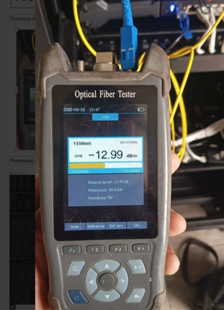
Measuring with an Optical Power Meter
An optical power meter is a device specifically designed for measuring the intensity of optical power. Through it, we can accurately measure the TX power and RX power of the SFP optical module. Before use, it is necessary to select the measurement wavelength to be consistent with the emission wavelength of the optical module. Then, connect the TX or RX interface of the optical module to the optical power meter through a converter and an optical fiber, and read the measurement value of the optical power meter. This value is the TX power or RX power of the SFP optical module. It should be noted that we need to ensure the cleanliness of the optical interface and the end face of the optical fiber to avoid contamination of the optical fiber end face or the optical interface by dust and other dirt, which may affect the measurement result.
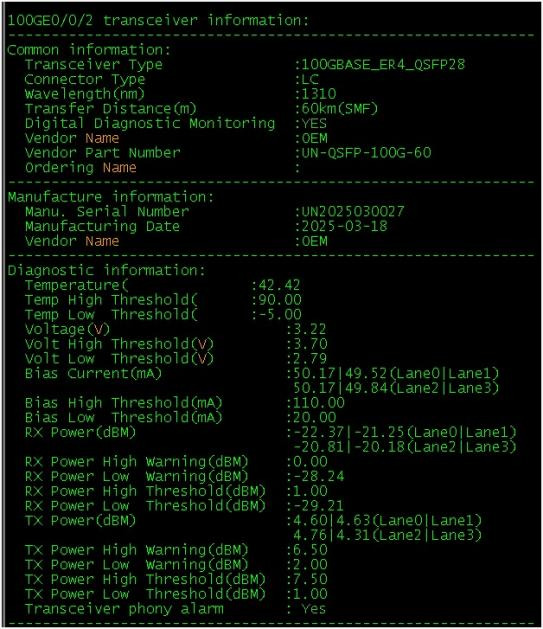
Monitoring Through the DDM Function of the SFP Optical Module
All SFP optical modules are equipped with DDM digital diagnostic monitoring function. They can monitor parameters such as the working voltage, working current, TX optical power and RX optical power inside the SFP optical module. Through the DDM function, we can also obtain the TX power and RX power of the optical module. However, it should be noted that the values read by DDM are approximations and may differ from the actual optical power. According to industry standards, the range within ±3 dB is acceptable.
Conclusion
Through this article, we have learned about the TX power and RX power of the optical module, understood their functions, and also knew how to measure and monitor them. We hope this will be helpful to you and enable you to have a better understanding of the various parameters of the optical module.
Share on Social:


